In this tutorial I will show you how you can integrate external axes, like positioners, tracks and the like into your Fuzzy Studio projects. You will see how with just a little bit of setup you can simulate the motion of any external axis in Fuzzy Studio and make sure that your process trajectories are regenerated on the fly. Please not that these examples will all use asynchronous axis motion, which means the axes and the robot will not be moving at the same time. For example, if we have a part with two sides and we can only reach one side at a time with the robot, rather than adding a second robot, we will simply turn the part 180 degrees with a positioner (or turn-table).

Setting up our digital twin with the Scene Tree tool
Within Fuzzy Studio, any 3D object can be positioned and moved relative to another, or relative to a user defined Reference Frame. To do this we first add our objects to the scene using the Scene Panel.
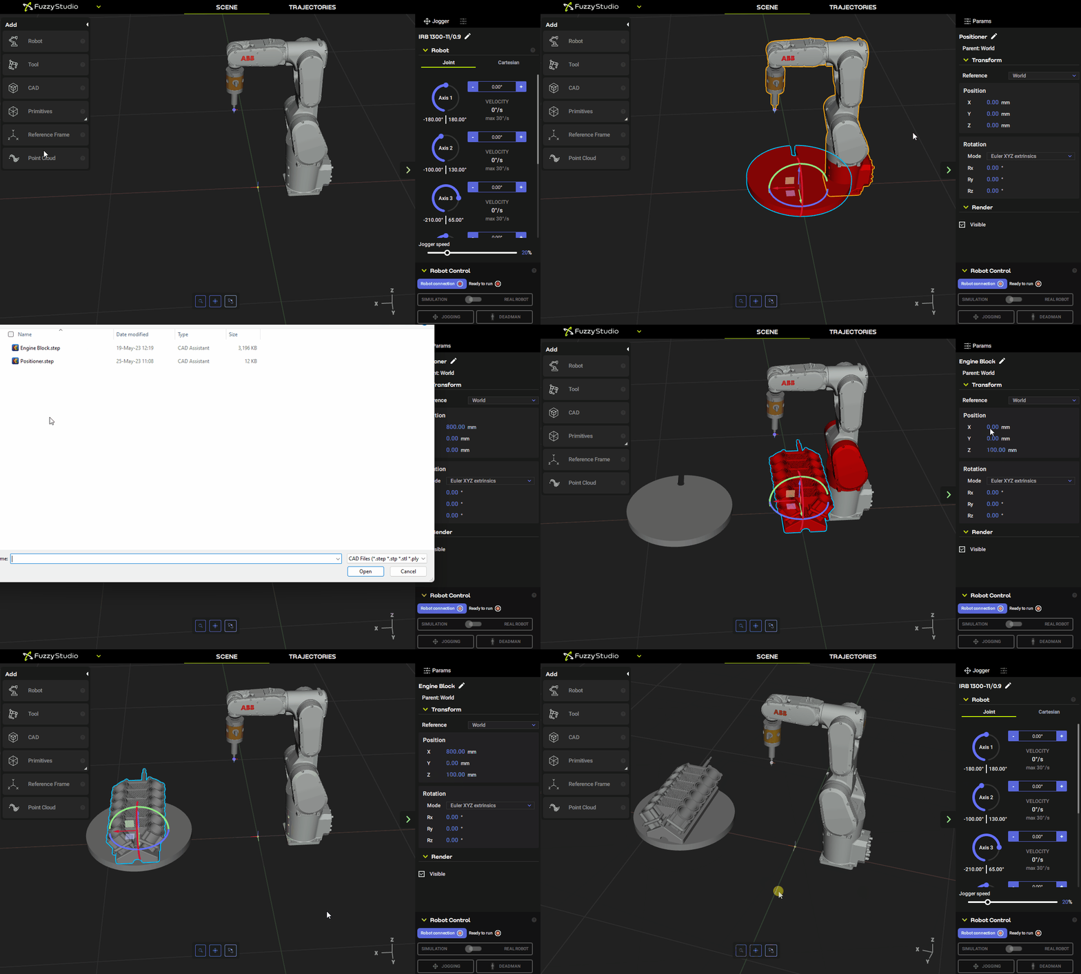
All of these objects are currently position with respect to the World frame of reference (the center of the grid in the scene). This is fine for quick setups but as our projects get more complex it is useful to introduce relative positioning (i.e. where one part is positioned with respect to another object or reference frame). To give an example, here we want the engine block to sit on the positionner table, and when the table turns, we want our 3D engine block to turn as well – just as it will in real life when the real table turns.
To create these relationships we use the Scene Tree tool.

As you can see, now my engine block is a child of my positioner and when I manually rotate the positioner so too does the engine block – voila!
This same principle can be used with tracks and pretty much any other moving parts.
As you can see, all objects in Fuzzy Studio move about their origins. These are typically set when creating the 3D model and can be modified if the origin is not practical for positioning purposes. For example, if the origin of my positioner is not at the center axis then when I rotate the object it will not stay “in place”.

Using I/O to update object positions programmatically
Now that our simple scene is set up, it would be very impractical for a real setting to have to manually move our objects in the scene every time the real objects are moved. So to solve this problem, Fuzzy Studio allows you to configure custom inputs that will automatically set an object’s position relative to another object or another frame of reference.
To do so, we use the Exchange Table Configuration tool.
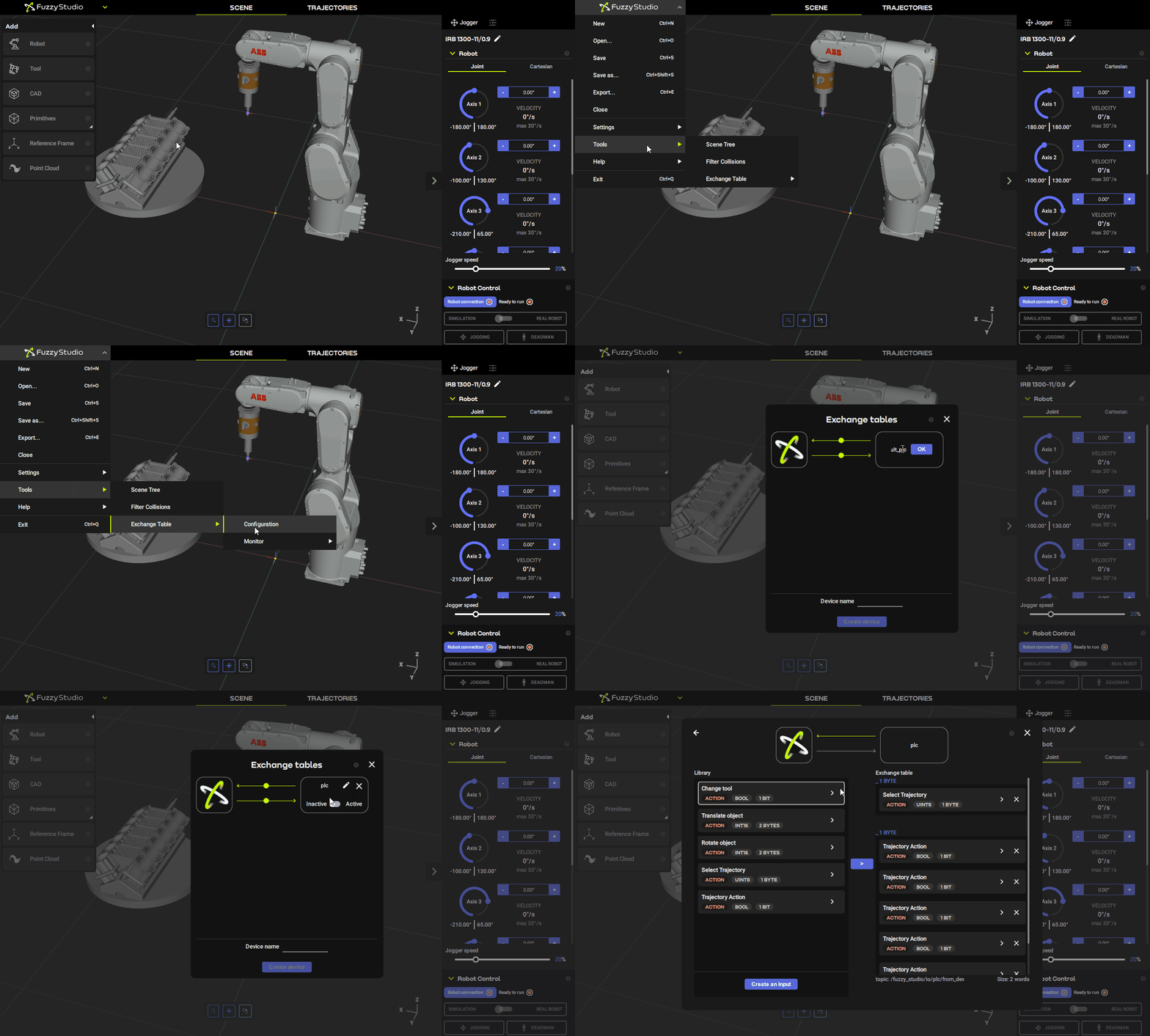
We then setup an input to rotate an object (as you can see there is also an input to move an object).
We start by deleting the default inputs that are configured for us and add our own Rotate object input. This input type has a few options. We want our table to rotate around it’s Z–axis and we are going to try to rotate by a certain amount of degrees each time this input is received. We will start by rotating with respect to the world reference frame just to see what happens.

To use this input, we will use Node-RED to simulate a MQTT payload from a PLC. Checkout our getting started tutorial with Node-RED if you haven’t already.
Our MQTT message will simply by a 1 byte buffer of Int16 with the desired angle to rotate by. Here we simply use 10 degrees. When it’s received, the positionner should rotate by 10 degrees.
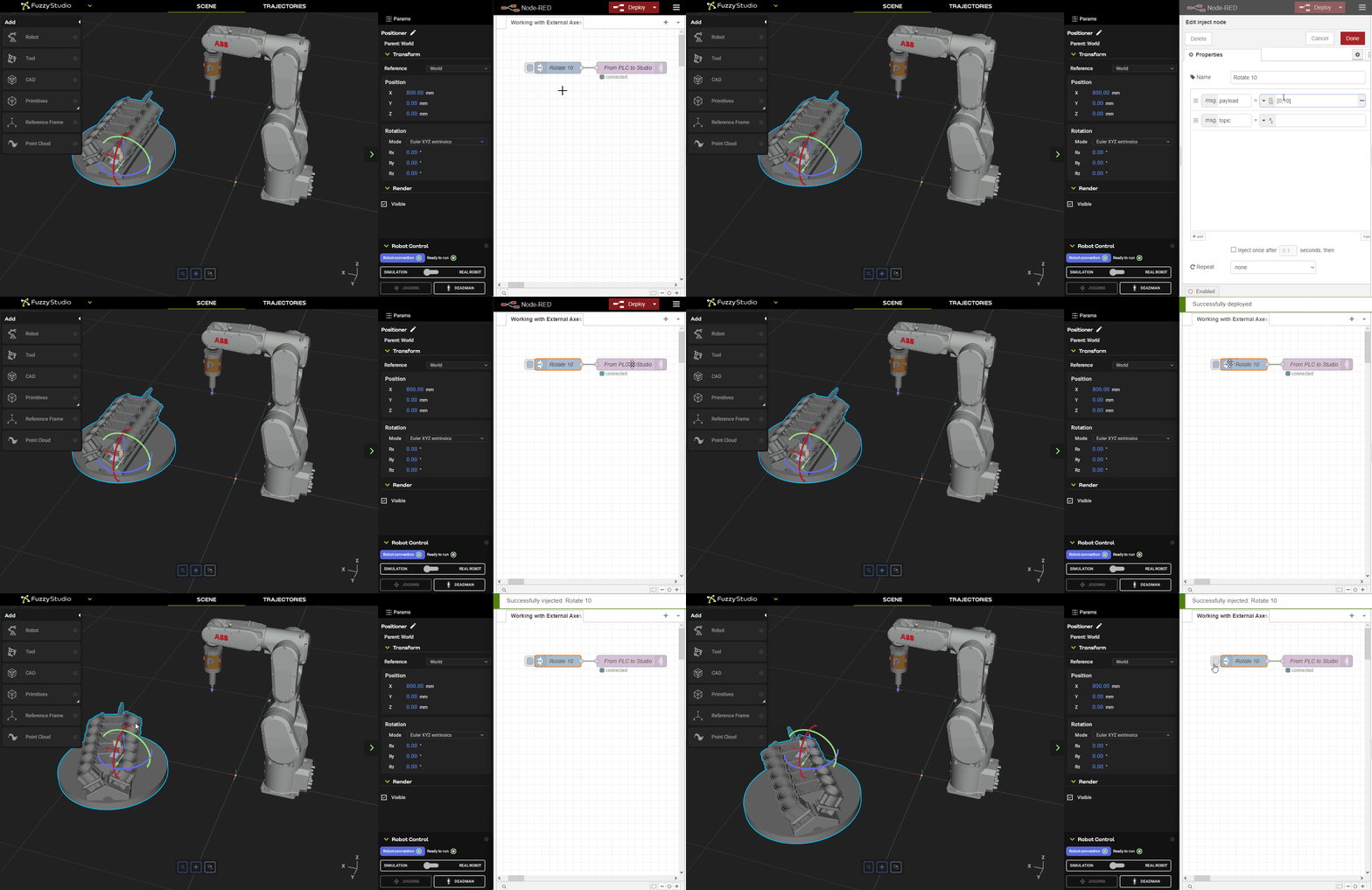
As you can see we are not rotating around the positioner’s axis but rather around the world’s axis! This is not what we want. To rotate around the positioner’s axis we are going to use a Reference Frame.
Using reference frames
Reference frames allow us to set up arbitrary points of interest around our workcell which can be used for any number of purposes. Most commonly they are used to calibrate trajectories to real world positioning (since there is always a little error between our simulated digital twin and the real deal).
Fuzzy studio allows you to create and customize as many reference frames as your heart desires!

Here we add a reference frame that is coincident with the positioner’s origin. This way, we can rotate around this reference frame and it will be like we are rotating around the positioner’s origin – just like we want.
Fixing our input
We now need to go back to the Exchange Table tool and modify our input to rotate with respect to our newly created reference frame.
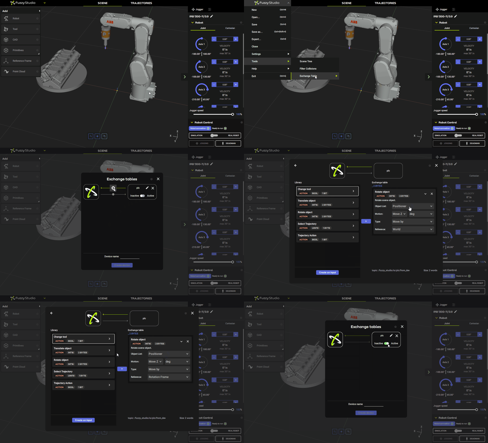
Now when we try out our input with Node-RED we see that we have successful configured the rotation around the positioner axis. Yeehaw.

We can also use the option to set the rotation angle directly rather than rotating by a certain amount. This will be more useful for our purposes today so let’s reconfigure and test this.
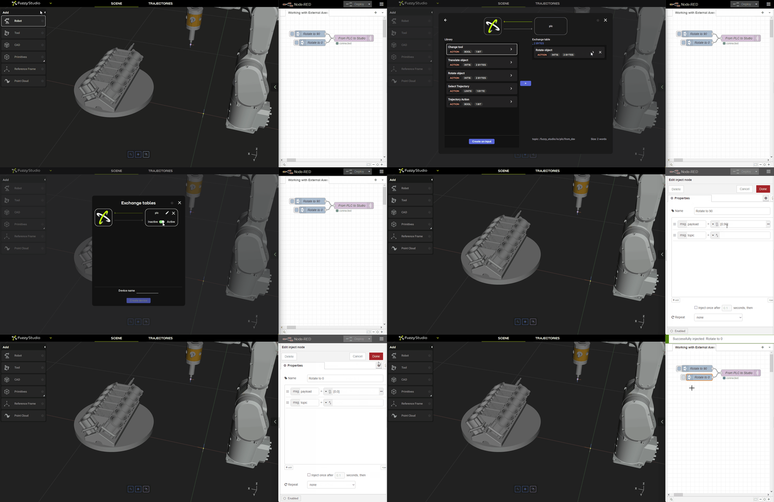
That looks good! Now let’s try it out with some trajectories too.
Setting up a basic sequence of trajectories and axis motions.
We start by making sure the positioner is where we want it to start – at 0 degrees of rotation, and we generate our first process trajectories. Here we are simulating a deburring application. We won’t do all of the engine cylinders to save some time, but we do need to do both sides.
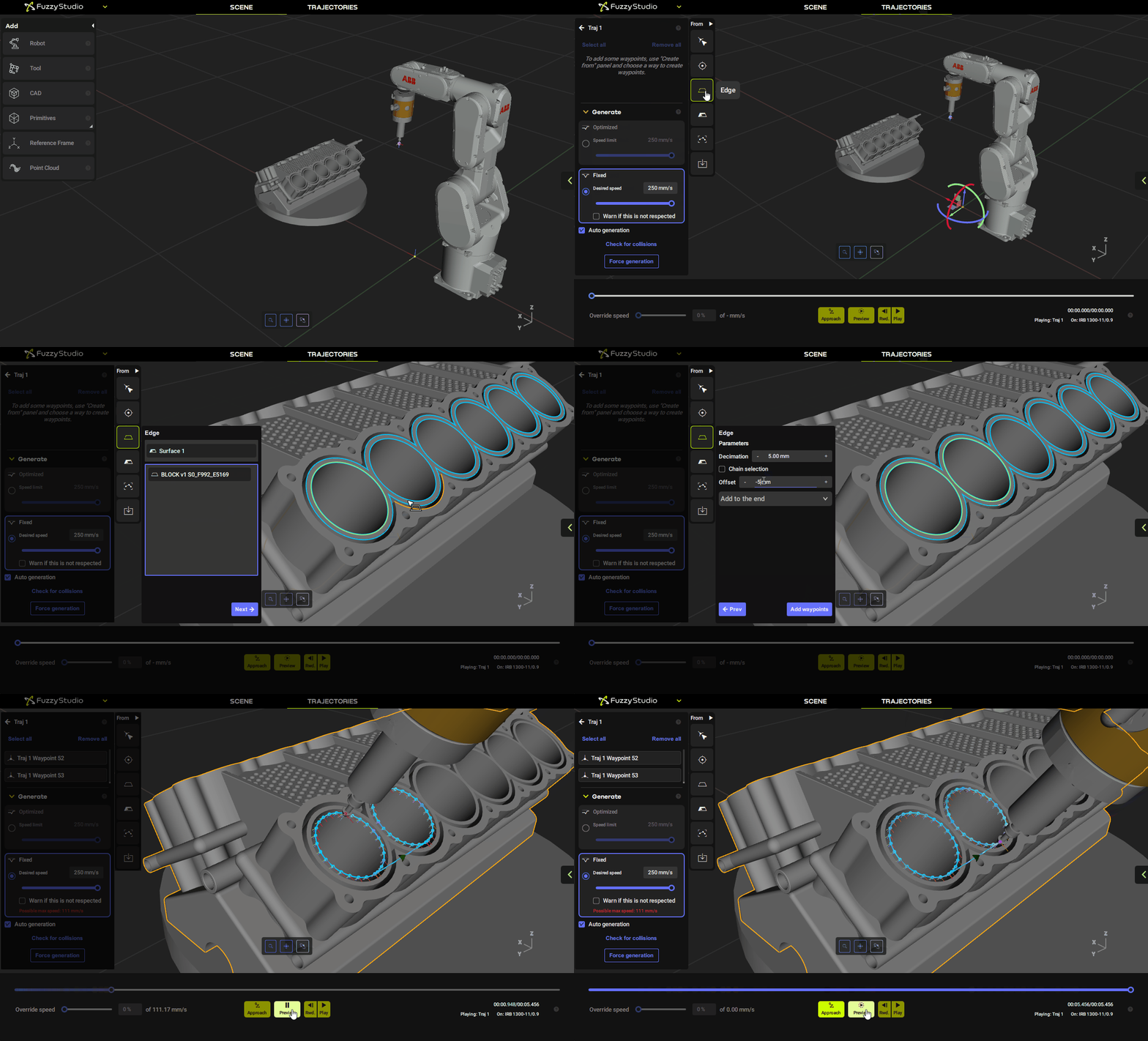
Once Traj 1 is finished we need to make it a child of the engine block object – so that it moves when the engine block moves.
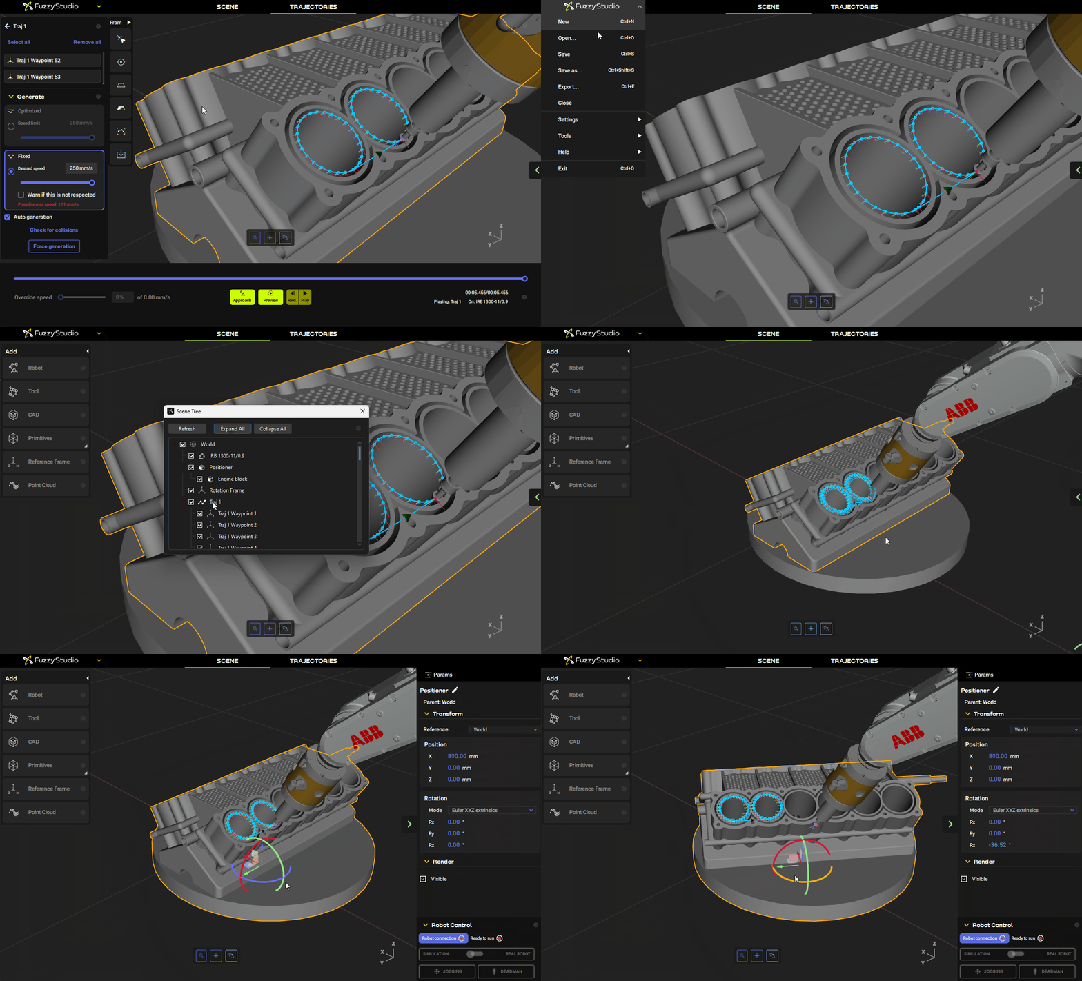
Now when we go to rotate the positioner by 180 degrees manually, the trajectory will “stick” to the engine block. We then make our second trajectory, Traj 2 in the same way and attach it to the engine block as well.
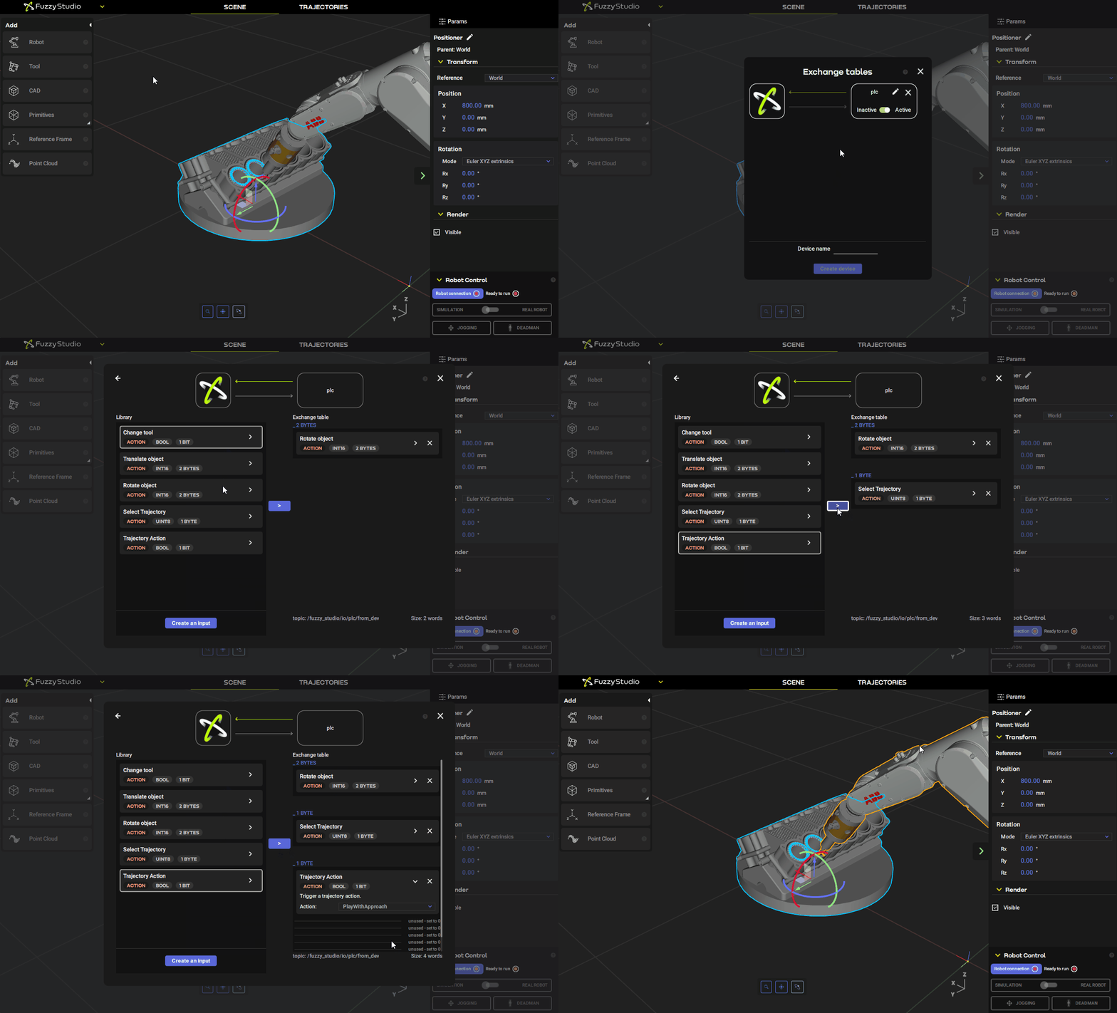
Finally we can simulate our sequence of positioner rotations and deburring operations with a few more simple Node-RED nodes and a couple of inputs.
⚠️ One important thing to remember is that if we are using the rotate input in absolute terms (like we are here) then if we leave 0 for that input in our exchange table then the positioner will rotate to 0 degrees! We don’t want this, so we need to make sure to always include the desired positioner rotation in degrees every time we send a new exchange table buffer.

Now you are all set and the sky is the limit with what you can accomplish with these simple yet powerful tools!
