In this tutorial, we will learn what Node-RED is and how it can be used to build robotic automation workflows with Fuzzy Studio. We will start with some general concepts and principles to get our very first robotic cycle working. By the end of this tutorial, you will be able to launch a robotic process from Node-RED and simulate a basic welding cycle in Fuzzy Studio.
Why Node-RED?
We designed Fuzzy Studio to make it easy for anyone to program, simulate, and control industrial robots. But industrial robots are only the tip of the automation iceberg. Our robots need to communicate with the outside world, i.e. PLCs, tooling, sensors, etc.
Let’s say we want to weld with a robot. First, we need to show the robot where the welds need to go and how fast the robot should move the weld torch in Fuzzy Studio. Then we need to “tell” the weld torch to turn on when the weld is supposed to start and turn off when the weld is finished. Imagine if you were learning how to weld, your teacher would show you where to weld, with what angle and approximate speed, then you do it by pulling the weld torch trigger and welding the parts. The robot needs to do the same.
We can also imagine that we might share process-specific information with the welding station like feed-rate, amperage, waveform, etc. All of this, as you will see in future tutorials, is possible. The point of this tutorial is not to master the intricacies of getting a beautiful and strong weld bead but rather to have a real-world application context to learn our two new tools: Fuzzy Studio and Node-RED.
So today we will focus on making a simple weld trajectory and configuring inputs and outputs (I/O) on that trajectory to make the weld torch turn on and off.
In a typical robotic workcell, the task of calling up different trajectories, turning on I/O, and generally being the automation maestro is up to Programmable Logic Controllers (PLCs). PLCs are industrial microcontrollers designed to interface with software and hardware in a very robust package. If you are familiar with Arduino microcontrollers – it’s basically the same principle but with a few caveats we won’t look at here.
PLCs provide a central location to manage all automation cycles and orchestrate the entire workcell. This is one of their primary usages. Today we will be using Node-RED to fill this role and simulate what a PLC could do in our workcell.
Please note that programming in Node-RED is nothing like programming a PLC. There are some very fundamental differences, but the end result we are looking for is the same: a system that allows us to interact with our robot as well as all of its surrounding equipment. What’s more, it is open-source and free for anyone!
So let’s dive into Node-RED just a bit more.
What is Node-RED and how do you get it?
For the purposes of this tutorial, Node-RED will be used as a PLC simulator, but it is much more than that. As stated on their website:
Node-RED is a programming tool for wiring together hardware devices, APIs, and online services in new and interesting ways.
It provides a browser-based editor that makes it easy to wire together flows using the wide range of nodes in the palette that can be deployed to its runtime in a single click.
I couldn’t have said it better myself!
I highly recommend checking out their website and tutorials to get a feel for all the amazing things you can do with the tool.
For now, start by following their download and installation instructions.
https://nodered.org/docs/getting-started/local
Once you have gotten up and running, you should see this interface in your browser at the following address (http://127.0.0.1:1880/):

For this tutorial we need to add some nodes to our Node-RED Palette.
node-red-dashboardnode-red-contrib-ui-ledTo do so, simply go to the palette manager and install them.

Now, let’s jump over to Fuzzy Studio.
Setting up Our Welding Example
Since other tutorials already cover how to set up the 3D scene (adding robots, tools, and CAD), we won’t delve into that here. Instead, we’ll start with this very basic welding example.

We have a FANUC robot equipped with a welding torch that needs to perform a saddle weld on this T-junction. For visual simplicity, there is no supporting or safety equipment in the scene, but they would be necessary in a real workcell.
Our right-side weld trajectory consists of several approach waypoints followed by the saddle weld and a few exit waypoints. The approach and exit waypoints ensure that the robot moves out of the way of the part so it can be removed.
To keep things clear, the start and end waypoints of the weld have been labeled.

With this basic trajectory in place, we will now configure our inputs and outputs in order to create a binary exchange table that can be used to communicate with a PLC. In our case here, we will use Node-RED!
Adding Inputs and Outputs (I/O) to create an Exchange Table.
The I/O management tools in Fuzzy Studio are a powerful and flexible way to connect your robot with external equipment. Detailed documentation can be found here, and further configuration parameters are explained in depth on this page.

For our first attempt, we will keep things simple. We will begin by creating a new device called “plc”. Then, we will configure the inputs (data coming from the PLC and going to Fuzzy Studio). For our example, we need two pre-configured inputs: “Select Trajectory” and “Trajectory Action”. “Select Trajectory” enables us to choose the trajectory we want to execute from our list of trajectories by its index (starting from 1). “Trajectory Action” can be configured to do multiple things, but we will set it to “Play with Approach”. This means that when this action is executed, if the robot is not exactly at the starting waypoint of the trajectory, it will automatically create an initial approach trajectory, execute that, and then execute the desired trajectory.

We can then configure our outputs. In this tutorial, we want to instruct the welding station to turn the torch on when the saddle weld starts and to turn it off when the weld ends. Since this is not one of the pre-configured outputs available, we will create it.

We first give it a name, a type (in this case, a boolean for ON/OFF is best), and a description so we know what it’s for.
Adding I/O to Trajectory Waypoints
Once our I/O is configured, we need to “Activate” our exchange table. Once activated, we can access our library of configured I/Os and use them as we please for any of the trajectory waypoints. In this case, we are going to add the “Weld Torch ON/OFF” output to the “Weld Start” waypoint and set it to 1 (or True). We will also add the same output to the “Weld End” waypoint but set it to 0 (or False).

And that’s it, our I/O is configured and our exchange table is ready to be used.
What is an “Exchange Table”?
Before we jump into Node-RED, I just want to clarify what we mean by an exchange table in Fuzzy Studio.
If we look back at the Exchange Table configuration step, we can see that the tool shows us a layout of bytes or words based on the I/O that we configured.


Depending on the type of I/O, the number of bits needed to represent its value may differ. Our official documentation explores this in depth if you are interested. For our inputs, Select Trajectory is represented by an 8-bit integer value, so it is 1 byte/word long, and Trajectory Action is a simple boolean (do we do the action or not) and is represented by a single bit. Since the minimum amount of information that we can represent in most systems is a byte, or 8 bits, we have to create a whole second byte/word just to hold our Trajectory Action input data. This makes our input exchange table two bytes/words long in total, with only the 1st bit of the 2nd word being used for something. In binary, this looks like:
  00000000   0    000 0000
| Select T | TA | ...
Our output exchange table, on the other hand, only has one configured output that requires only 1 bit, so the entire table is only 1 byte/word long.
Finally, this information needs to be shared with other devices that require it. For this, Fuzzy Studio uses MQTT to send and receive data over “topics.”

For more details on how MQTT works, please check out this link: https://mqtt.org/.
All we need to know here is that there are two main topics that you have to subscribe to if you want to send and receive data with Fuzzy Studio (your robot):
/fuzzy_studio/io/plc/to_device
/fuzzy_studio/io/plc/from_device
Where “plc” is the name of the device we created.
With this information, we can finally get started with Node-RED!
Configuring Our Node-RED Flow
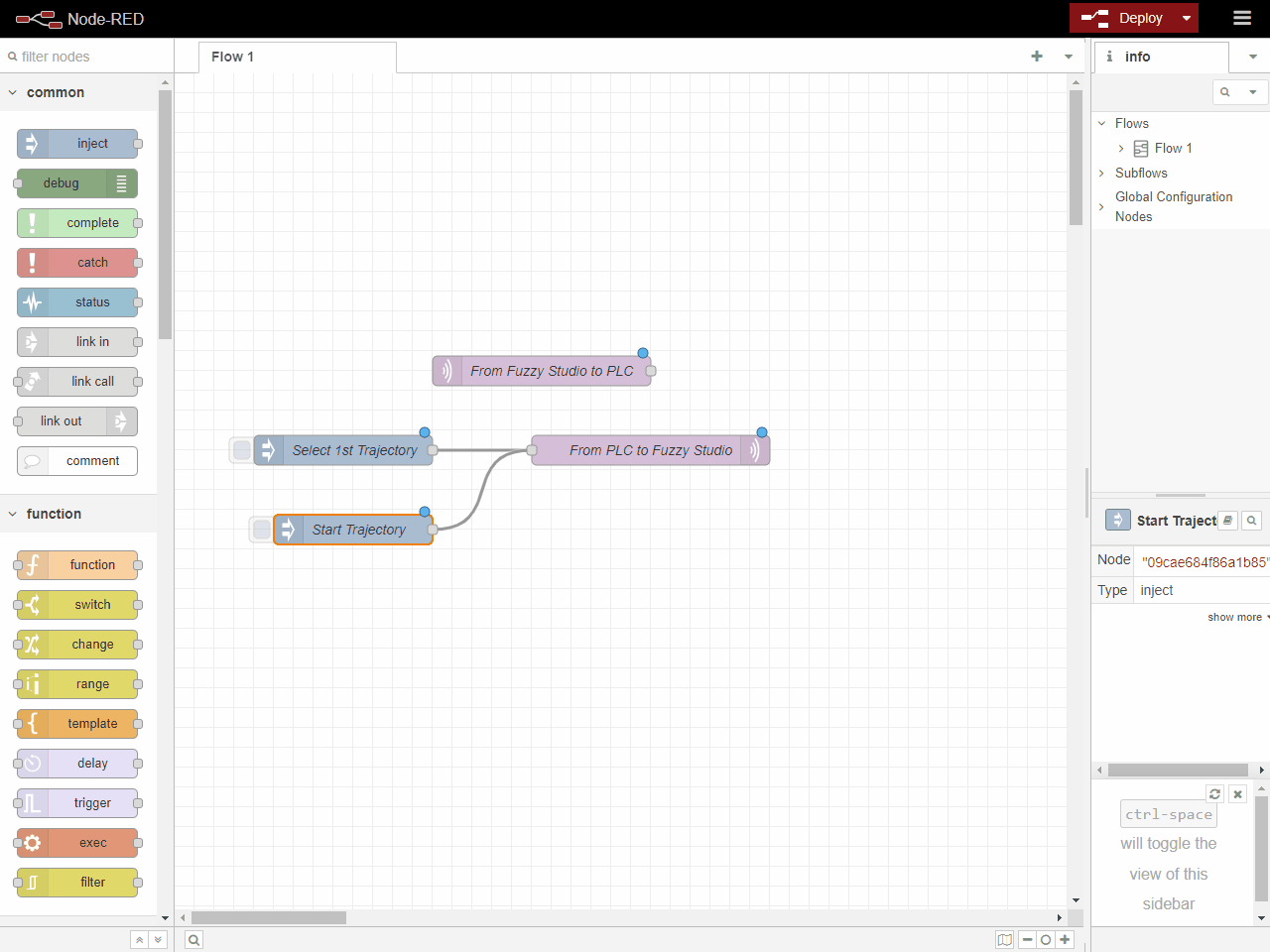
We start by adding publisher and subscriber nodes for MQTT in our flow.

To clarify, we name /fuzzy_studio/io/plc/to_device as “From Fuzzy Studio To PLC” and /fuzzy_studio/io/plc/from_device as “From PLC to Fuzzy Studio”. The default configurations will work fine.
Next, we add an inject node to act as a button to send a “message” to Fuzzy Studio through our MQTT nodes.
The first message we want to send is to tell Fuzzy Studio to select the trajectory we want, which has an index of 1.
We set the message “payload” to “buffer” format. The buffer format is an array of integer representations of bytes, i.e. 1 = 0000 0001, 2 = 0000 0010 … 128 = 1000 0000.
Luckily for us, we want to send an integer in the first byte because that is the index of the trajectory we want to select.
Even though we are only interested in the first byte/word of the message sent to Fuzzy Studio, we are obligated to fill out the whole table and all of its bytes/words. So we still put a 0 in the second byte of our buffer array: [1,0].

We will now create another inject node, this time to execute our trajectory action. We will follow the same steps as before, but this time our message payload will be different.
In the first byte, we want nothing but 0s because we are not trying to select a new trajectory. In the second byte, we need to set the very first bit to 1 if we want to execute the trajectory action. In binary, this looks like: 0000 0000 1000 0000. For our Node-RED buffer, we will write it like this: [0, 128] because 0000 0000 = 0 and 1000 0000 = 128 in integer format.

Finally, we want to verify if our weld torch is turning on and off at the correct times, so we need to listen to our MQTT input topic. To provide a visual indicator, we will add an LED node to our flow and configure it to turn red when the Weld Torch ON signal is 0 and green when it is 1. Since it is in the first bit of the only byte of our table, we represent the values in Node-RED with 0 and 128, respectively.
To see the LED in action, you need to open a browser window and go to http://127.0.0.1:1880/ui to open the Node-RED Dashboard.
Now all we’re left with is to test our communication and see if Node-RED is really talking to Fuzzy Studio.

And if Fuzzy Studio is communicating with Node-RED (turning our welding torch on and off at the right times).

Looking good!
Our first basic welding cycle!
With all of our parts in place, we can sit back, kick our feet up, and start profiting! Well, not quite… but from here, it’s pretty easy to see how you can integrate Fuzzy Studio into a standard automation workflow and extend your robot’s capabilities through external automation systems. In our future tutorials, we will explore some of these many possibilities!

