Now that you’re familiar with the interface and know how to navigate between the different panels that will guide you to your greatest ideas, let’s get down to business.
The best way to learn how to use Fuzzy Studio is to try it out on a real application. Get ready to get your hands dirty with a complete walkthrough of an entire gluing application!

Setting up our scene
Create your project
The first step in building an application is to create a project, which you can either load from an existing project or create from scratch.
Here we will create one from scratch. So choose the New project option.
Fuzzy Studio works with a project system: this means that a project contains the paths to each CAD used in it, their positions, all the trajectories created and some user settings.
Once you’ve created your project, you’ll come to the Scene panel. This is where you’ll build your environment. Of course right now the whole scene is completely empty, but we’re about to add a bunch of stuff to it! We bet that in 5 minutes you will be surprised by the results already achieved?
Setup your robot
Pick your robot
We’re trying to create a robotic application so obviously the first thing that we want to add is a robot !
Click on the Add Robot Button to get to the robot Library, then for our application we consider that the Fanuc M-20iA/20M is the right match. You can scroll through the list of available options or just search for the Fanuc M-20iA/20M using the search bar.
Fuzzy Studio provides a robot library that allows you to use any robot supported by our software, regardless of the brand or controller. Supported brands include Fanuc, ABB, Kuka, Yaskawa, Staübli and Universal Robots.
Add a tool to your robot
It’s nice to have a robot, but without a tool attached to it, we agree it won’t be much use!
Fuzzy Studio provides a Tool Library which comes with a few generic starter tools but is primarily to be customized by you directly.
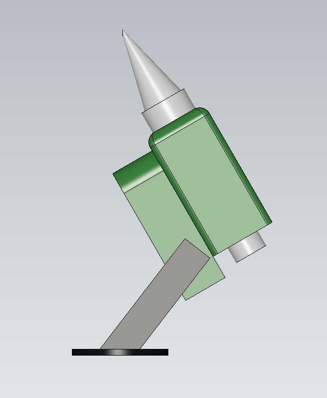
Here the tool we need for our gluing process is not present in our custom tool database, so we’re going to create one. For this exercise, we have attached the CAD file that corresponds to tool and the corresponding image, please download them from the following links.
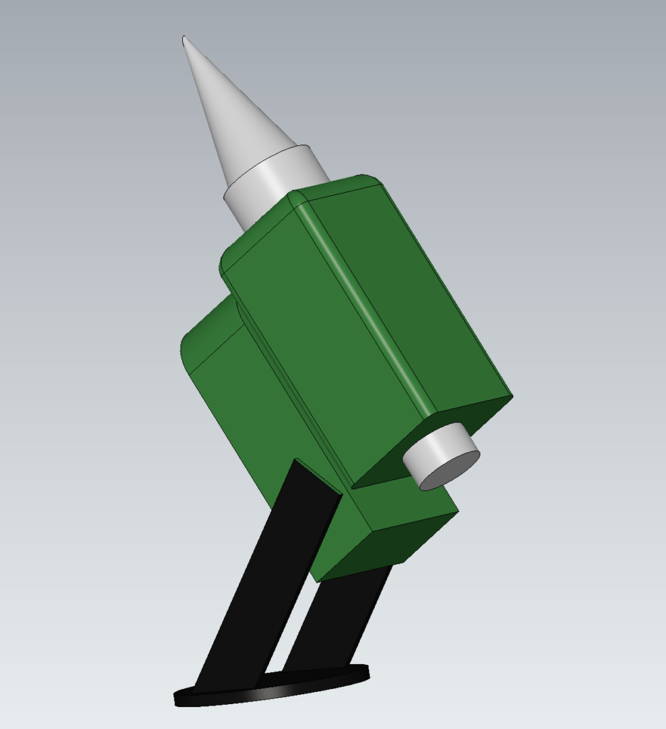
Most applications require specific or custom tooling that might not be present in our database. That’s why we allow users to create their own tooling for Fuzzy Studio. In order to do so you need to get to the Tool Library to click the Add new option :
Choose a name, attach a 3D model of your tool and a thumbnail image to make it easier to find your tool in the library.
Our tool needs both a TCP (Tool Center Point) and an Attach point that define its point of interest in its CAD referential.
The TCP is the interest point that we’re going to manipulate and that is the virtual object that is going to follow all of our trajectories. For a sander it corresponds to the center of the grit paper, for a welding torch it is the tip of the welder… It is a crucial notion to any robotic application, whether it is using Fuzzy Studio or not.
An attach point is needed in order to set where the center of the attach point between the tool and the Flange of the robot is.
In order to add a TCP and an attach point you need to click the + button under the image Box. You can set multiple TCPs and switch between them during your application setup.
Here our TCP and attach points are declared as such :


We have made life easy here because the origin of the CAD is already centered on the mounting point, and the orientation of the CAD and the FANUC flange match, so we can keep the mounting point at 0 for each element. Most of the time we have to find the right transformation data to get the 3D tool positioned correctly with respect to our robot flange.
Then you can save our tool and select it in the library! Your saved custom tools are now available in the Tool Library for any projects you might create!

Wou now have a Robot with a tool attached.
Then you need to add our environment model to simulate collisions and visualize the robot in its general environment to be as close to reality as possible!
Integrate your environment
Add your environment model
Here you will first add our robot’s cage which you can download here:

Now you’ve imported your environment but nothing is placed correctly. You need to move everything to it’s right place!
Scene object manipulation
All objects in the Scene panel are moved in the same way. To set the exact position of the environment, select it, open the right panel and set the values manually.

Here the environment needs to be set at:
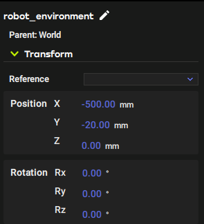
And the Robot‘s position needs to be set to :

To change the robot’s position and access its parameter panel, select the robot and navigate to the parameter panel at the top of the right panel. The process is shown in the following GIF!
Here you don’t need to move the robot base, but it can be very useful for some more complex robot cells.

Your cell is now complete. However, it won’t be much use if you don’t have a piece to work on, so let’s add one!
Add your work piece
Just as you imported the CAD model of our environment, add the part you want to bond. For this tutorial, we have chosen a simple model of a car door, which provides us with some challenging geometries to glue (or more commonly, seal).


Then place it at the right position:

Congratulations, you have just created a robotic application cell. A robotic cell, even the most powerful one, often consists of the following elements: a robot, a tool, a safety element, a part to be machined, and, depending on the situation, an infeed and an outfeed. Keep this in mind when creating your own solution. You can do whatever you want with Fuzzy Studio.
You are now ready for the second part of the design: the creation of trajectories!
