In this tutorial, we will create a simple painting application using a single industrial robot. We will explore the basic steps one can take to go from nothing to a basic version of the painting process. While I will use the term “painting” in this tutorial, the following is applicable to pretty much any spraying or pulverization application (e.g. powder coating, enameling, dye penetrant coating, sandblasting…). Programming robot trajectories for these kinds of applications is notoriously difficult, but as you will see, with Fuzzy Studio, not only can it be really easy – you don’t have to do any programming!
Process criteria
For this example, we want to cover the part (plane propeller) with a pulverized coating. We will try to cover the entire surface, including the flange mount, but typically, there are portions of the surface that will be masked or covered to prevent them from being painted, or simply because they are in some sort of holder.
We want to cover as much of the part as possible without having to reposition it.
We only have one robot to work with.
Creating the scene
We are starting from a blank slate here, so let’s first add our robot and select our tool. You can download the FSTOOL file here.
Now we will import our part refence – in this case our plane propeller – download here. This part comes courtesy of https://grabcad.com/library/2-propeller-2.
We will start by positioning the propeller approximately in front of the robot. As you can see, the propeller has a complex geometric shape. Normally, this makes applying an even coat of paint more challenging because it is harder to stay perpendicular to the surface and maintain the right distance. However, as you will see later, our waypoint generator will make short work of this problem.

But first, let’s get rid of the collision detection between our tool’s “spray cone” and the propeller. The cone is simply here to help us visualize the spray of paint, and we don’t care if it is in contact with the propeller.
To do this, we will add a collision filter. Go to View > Filter Collisions.
In the window, create a filter between the propeller and the tool. Click Create and then OK. You will now see that collisions between the tool and the propeller are ignored, but collisions with the robot and the propeller remain.
Positioning our part (Reachability)
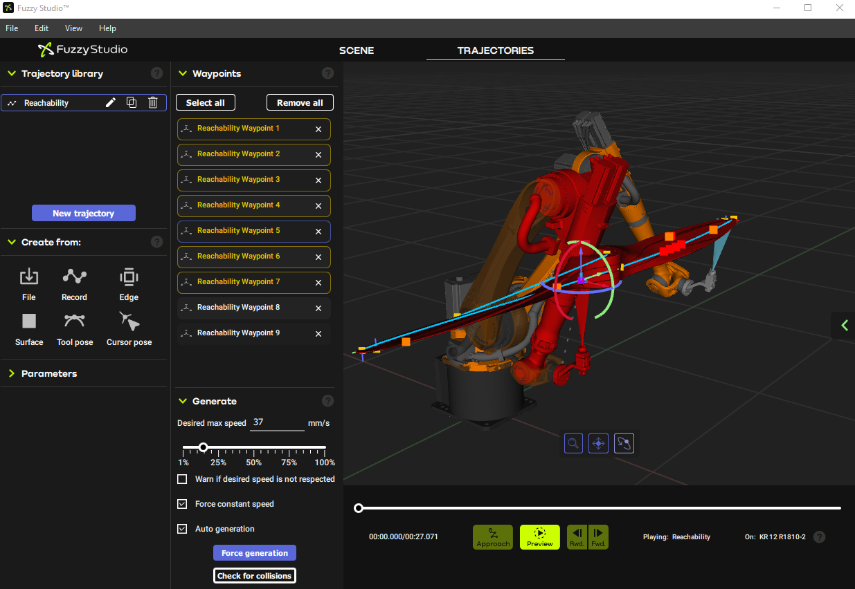
We have only approximately positioned our part at this point, and we need to make sure that our robot can reach all corners of the part. This is known as reachability. A good way to test this is to create a new trajectory, which we will call Reachability, and add waypoints at the extremities of the part as shown below.
We are not concerned yet about how the robot moves from waypoint to waypoint, but rather that the robot can reach each waypoint and reach them without colliding.
We see in this example that although the robot can reach all of the waypoints, the waypoints closest to the robot cause the robot to collide with the propeller.
To fix this, we need to move the propeller. However, if we move the propeller, we will have to recreate the Reachability trajectory. To avoid this, we can make the Reachability trajectory a child of the propeller using the Scene tree tool. Go to View > Scene tree and simply drag and drop the trajectory onto the propeller. Now, when we move the propeller, the trajectory will move with it!
After a small adjustment, we can see that the robot no longer collides with the propeller, and we can start with our actual painting trajectories.
Creating our painting trajectories
Let’s begin by creating a new trajectory and naming it “Paint-TOP”. Feel free to name your trajectories however you see fit.
For the propeller, I think the Cursor pose tool is our best bet. This waypoint generator simply adds a waypoint at the intersection of the cursor and the surface it is on. What’s nice is that it gives you a point that is at the right distance to the surface and perpendicular as well! Hooray for Cursor pose!
Disclaimer: I am not a professional painter, so this is just how I would do it if I were going to do it by hand. But that is the beauty of Fuzzy Studio – you can simply show the robot where to go without having to code. And if a pro were doing this in my place, she would probably want to do it her way. No problemo!
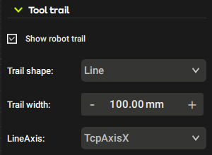
Now our first trajectory looks pretty good, but we don’t know if our surface is entirely covered. So, we will use a nifty little tool called Show robot trail. This tool is available when a trajectory is selected and leaves a purple trail where the robot’s TCP has passed. Think of slime behind a snail.
When we activate this tool, we immediately see where we are missing some spots. Please note, however, that if the robot trajectory goes a little above or below the propeller surface, that spot will still get painted, albeit less optimally.
Here we have a small section in the middle that requires a bit more elaboration.

All we need to do is use the Cursor pose tool once more and continue adding waypoints.

Things are definitely looking better, but there is still a patch that I want to make sure we hit correctly. This means I need to insert a new waypoint between two other points. To do this, I select the waypoint just upstream of where I want to add another and then use the “Cursor pose” tool, but this time I change the rule to add after rather than to the end. I click in the area where I want the waypoint, and this inserts my new waypoint right after the one I had just selected.
Finally, I’m no pro, but I do know that you shouldn’t stop your spray on the part. You need to go outside the part before the spray stops. This is affectionately referred to as overspray. To achieve this in Fuzzy Studio, all we need to do is modify the waypoints at the propeller tips to be just a bit outside the propeller.
And that’s all there is to it!
We still have some work ahead of us to fully paint this part, but we will look at that in Part 2.
What’s next…
- Finishing our painting trajectories.
- Adding reconfiguration trajectories to get from one painting trajectory to the next.
- Planning for a part support
- Adding protective barriers.
- Configuring I/O.
- Testing our process in simulation.
